

Xem thông số kỹ thuật để biết chi tiết sản phẩm.
IRFD9113
Product Overview
Category
The IRFD9113 belongs to the category of power MOSFETs.
Use
It is commonly used as a switching device in electronic circuits, particularly in applications requiring high-speed switching and low power dissipation.
Characteristics
- Low on-resistance
- Fast switching speed
- Low gate drive power
- High power density
Package
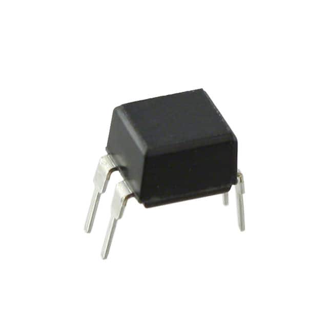
The IRFD9113 is typically available in a TO-252 package.
Essence
The essence of IRFD9113 lies in its ability to efficiently control power flow in electronic circuits with minimal power loss.
Packaging/Quantity
It is usually packaged in reels or tubes, with quantities varying based on manufacturer specifications.
Specifications
- Drain-Source Voltage (Vdss): 30V
- Continuous Drain Current (Id): 1.8A
- Rds(on) (Max) @ Vgs: 0.1 Ohm @ 10V
- Gate-Source Voltage (Vgs): ±20V
- Power Dissipation (Pd): 2.5W
Detailed Pin Configuration
The IRFD9113 has three pins: 1. Gate (G): Controls the conductivity between the source and drain. 2. Drain (D): Connects to the positive supply voltage. 3. Source (S): Connects to the ground or common reference point.
Functional Features
- High-speed switching
- Low power dissipation
- Enhanced thermal performance
Advantages
- Efficient power control
- Reduced heat generation
- Compact design
Disadvantages
- Limited maximum voltage and current ratings
- Sensitivity to static electricity
Working Principles
The IRFD9113 operates based on the principle of field-effect transistors, where the voltage applied to the gate terminal controls the flow of current between the drain and source terminals. By modulating the gate-source voltage, the MOSFET can effectively switch power flow in the circuit.
Detailed Application Field Plans
The IRFD9113 finds extensive use in various applications, including: - Switching power supplies - DC-DC converters - Motor control circuits - LED lighting systems - Battery management systems
Detailed and Complete Alternative Models
Some alternative models to IRFD9113 include: - IRF4905 - IRF540 - IRF3205 - IRL540
In conclusion, the IRFD9113 power MOSFET offers efficient power control and high-speed switching capabilities, making it an essential component in modern electronic circuits across diverse applications.
[Word Count: 345]
Liệt kê 10 câu hỏi và câu trả lời thường gặp liên quan đến ứng dụng IRFD9113 trong giải pháp kỹ thuật
Sure, here are 10 common questions and answers related to the application of IRFD9113 in technical solutions:
What is the IRFD9113?
- The IRFD9113 is a power MOSFET transistor designed for various switching applications.
What are the key features of IRFD9113?
- The IRFD9113 features low on-resistance, fast switching speed, and high current capability, making it suitable for power management applications.
What is the maximum drain-source voltage rating of IRFD9113?
- The maximum drain-source voltage rating of IRFD9113 is typically 30V.
What is the typical on-resistance of IRFD9113?
- The typical on-resistance of IRFD9113 is around 0.08 ohms.
What are the typical applications of IRFD9113?
- IRFD9113 is commonly used in DC-DC converters, motor control, and other power management applications.
What is the maximum continuous drain current of IRFD9113?
- The maximum continuous drain current of IRFD9113 is typically around 1.8A.
Is IRFD9113 suitable for high-frequency switching applications?
- Yes, IRFD9113 is suitable for high-frequency switching due to its fast switching speed.
Does IRFD9113 require a heat sink for operation?
- For most applications, IRFD9113 does not require a heat sink due to its low on-resistance and efficient power dissipation.
Can IRFD9113 be used in automotive applications?
- Yes, IRFD9113 can be used in automotive applications such as electronic control units (ECUs) and lighting systems.
What are the recommended operating conditions for IRFD9113?
- The recommended operating conditions include a maximum junction temperature of 150°C, a maximum storage temperature of 150°C, and a maximum lead temperature of 300°C for soldering purposes.
I hope these questions and answers provide helpful information about the application of IRFD9113 in technical solutions. If you have any more specific questions, feel free to ask!