

Xem thông số kỹ thuật để biết chi tiết sản phẩm.
Encyclopedia Entry: 74ALVC16244ADGGRE4
Product Information Overview
- Category: Integrated Circuit (IC)
- Use: Buffer/Driver
- Characteristics: High-speed, low-power, non-inverting, 16-bit bus buffer/driver
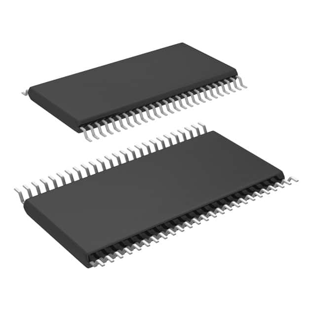
- Package: TSSOP (Thin Shrink Small Outline Package)
- Essence: The 74ALVC16244ADGGRE4 is a high-performance buffer/driver designed for use in various digital applications. It provides non-inverting buffering and driving capabilities for a 16-bit bus.
- Packaging/Quantity: The 74ALVC16244ADGGRE4 is typically packaged in reels or tubes, with a quantity of 2500 units per reel/tube.
Specifications
- Supply Voltage: 1.2V to 3.6V
- Input Voltage Levels: VIL = 0.8V, VIH = 2.0V
- Output Voltage Levels: VOL = 0.1V, VOH = VCC - 0.1V
- Operating Temperature Range: -40°C to +85°C
- Propagation Delay: 2.5ns (max) at 3.3V supply voltage
- Output Drive Capability: ±24mA
- Input Capacitance: 4pF (typical)
Detailed Pin Configuration
The 74ALVC16244ADGGRE4 has a total of 48 pins, arranged as follows:
``` Pin Configuration Diagram ------------------------
          1   A1
          2   Y1
          3   GND
          4   Y2
          5   A2
          6   Y3
          7   GND
          8   Y4
          9   A3
         10   Y5
         11   GND
         12   Y6
         13   A4
         14   Y7
         15   GND
         16   Y8
         17   A5
         18   Y9
         19   GND
         20   Y10
         21   A6
         22   Y11
         23   GND
         24   Y12
         25   A7
         26   Y13
         27   GND
         28   Y14
         29   A8
         30   Y15
         31   GND
         32   Y16
         33   VCC
         34   OE#
         35   GND
         36   G1#
         37   G2#
         38   GND
         39   G3#
         40   G4#
         41   GND
         42   G5#
         43   G6#
         44   GND
         45   G7#
         46   G8#
         47   GND
         48   GND
```
Functional Features
- Non-inverting buffer/driver for a 16-bit bus
- High-speed operation with low power consumption
- Wide supply voltage range allows compatibility with various systems
- Output drive capability enables driving of capacitive loads
- ESD protection on all inputs and outputs for enhanced reliability
- 3-state output control for bus sharing applications
Advantages and Disadvantages
Advantages: - High-speed operation ensures efficient data transfer - Low power consumption helps in reducing overall system power requirements - Wide supply voltage range allows for compatibility with different systems - ESD protection enhances reliability and robustness - 3-state output control enables bus sharing applications
Disadvantages: - Limited to non-inverting buffering and driving capabilities - May not be suitable for applications requiring inverting functionality - Sensitive to electrostatic discharge (ESD) events, necessitating proper handling and precautions
Working Principles
The 74ALVC16244ADGGRE4 is designed to buffer and drive a 16-bit bus. It operates by receiving input signals on the A1-A8 pins and providing corresponding non-inverted outputs on the Y1-Y16 pins. The OE# pin controls the output enable/disable function, allowing the device to be put into a high-impedance state when not actively driving the bus.
The IC operates within a specified supply voltage range and provides high-speed data transfer with low power consumption. It incorporates ESD protection on all inputs and outputs to enhance reliability and prevent damage from electrostatic discharge events.
Detailed Application Field Plans
The 74ALVC16244AD
Liệt kê 10 câu hỏi và câu trả lời thường gặp liên quan đến ứng dụng 74ALVC16244ADGGRE4 trong giải pháp kỹ thuật
Sure! Here are 10 common questions and answers related to the application of 74ALVC16244ADGGRE4 in technical solutions:
Q: What is the function of the 74ALVC16244ADGGRE4? A: The 74ALVC16244ADGGRE4 is a 16-bit buffer/driver with 3-state outputs. It is used to amplify and control signals in digital circuits.
Q: What is the voltage range supported by the 74ALVC16244ADGGRE4? A: The 74ALVC16244ADGGRE4 supports a voltage range of 1.65V to 3.6V, making it compatible with various logic families.
Q: Can the 74ALVC16244ADGGRE4 be used for bidirectional communication? A: Yes, the 74ALVC16244ADGGRE4 has bidirectional data flow capability, allowing it to be used for bidirectional communication between different parts of a circuit.
Q: What is the maximum output current of the 74ALVC16244ADGGRE4? A: The 74ALVC16244ADGGRE4 can source or sink up to 24mA of current per output pin, making it suitable for driving various loads.
Q: Is the 74ALVC16244ADGGRE4 compatible with TTL logic levels? A: Yes, the 74ALVC16244ADGGRE4 is compatible with both TTL and CMOS logic levels, providing flexibility in interfacing with different types of logic circuits.
Q: Can the 74ALVC16244ADGGRE4 be used in high-speed applications? A: Yes, the 74ALVC16244ADGGRE4 is designed for high-speed operation and can support data rates up to 400Mbps.
Q: Does the 74ALVC16244ADGGRE4 have built-in ESD protection? A: Yes, the 74ALVC16244ADGGRE4 has built-in ESD protection on all inputs and outputs, ensuring robustness against electrostatic discharge events.
Q: Can I use the 74ALVC16244ADGGRE4 in a mixed-voltage system? A: Yes, the 74ALVC16244ADGGRE4 supports mixed-voltage operation, allowing it to interface between different voltage domains within a system.
Q: What is the power supply voltage range for the 74ALVC16244ADGGRE4? A: The 74ALVC16244ADGGRE4 operates with a power supply voltage range of 1.2V to 3.6V, making it suitable for low-power applications.
Q: Are there any special considerations for PCB layout when using the 74ALVC16244ADGGRE4? A: Yes, it is recommended to follow the manufacturer's guidelines for PCB layout, including proper decoupling capacitors placement and minimizing trace lengths to reduce noise and ensure signal integrity.
Please note that these answers are general and may vary depending on specific application requirements. It is always recommended to refer to the datasheet and consult with the manufacturer for detailed information.