

Xem thông số kỹ thuật để biết chi tiết sản phẩm.
MC10E158FNR2
Product Overview
- Category: Integrated Circuit (IC)
- Use: Digital Logic
- Characteristics: High-speed, ECL-compatible, 8-bit D-type Flip-Flop
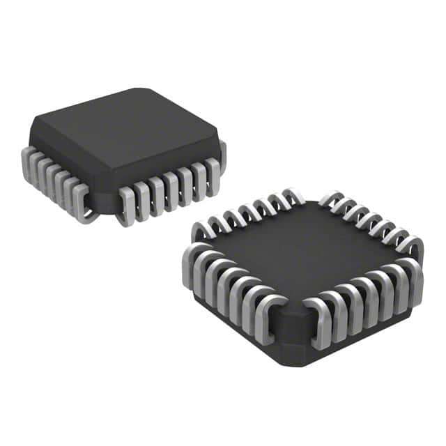
- Package: 28-pin PLCC (Plastic Leaded Chip Carrier)
- Essence: The MC10E158FNR2 is a high-performance flip-flop designed for use in digital logic circuits. It operates at high speeds and is compatible with Emitter-Coupled Logic (ECL) signaling.
- Packaging/Quantity: The MC10E158FNR2 is available in a 28-pin PLCC package. Each package contains one IC.
Specifications
- Supply Voltage: +5V
- Operating Temperature Range: -40°C to +85°C
- Propagation Delay: 1.5 ns (typical)
- Input Voltage Levels: ECL-compatible
- Output Voltage Levels: ECL-compatible
- Clock Frequency: Up to 1 GHz
- Data Input Format: TTL-compatible
- Output Format: ECL-compatible
Pin Configuration
The MC10E158FNR2 has a total of 28 pins. The pin configuration is as follows:
Pin 1:   VEE
Pin 2:   Q0
Pin 3:   Q1
Pin 4:   Q2
Pin 5:   Q3
Pin 6:   Q4
Pin 7:   Q5
Pin 8:   Q6
Pin 9:   Q7
Pin 10:  GND
Pin 11:  CLK
Pin 12:  D0
Pin 13:  D1
Pin 14:  D2
Pin 15:  D3
Pin 16:  D4
Pin 17:  D5
Pin 18:  D6
Pin 19:  D7
Pin 20:  VCC
Pin 21:  Qn
Pin 22:  Qn-1
Pin 23:  Qn-2
Pin 24:  Qn-3
Pin 25:  Qn-4
Pin 26:  Qn-5
Pin 27:  Qn-6
Pin 28:  Qn-7
Functional Features
- High-speed operation: The MC10E158FNR2 is designed to operate at high clock frequencies, making it suitable for applications that require fast data processing.
- ECL compatibility: The IC is fully compatible with Emitter-Coupled Logic (ECL) signaling, allowing seamless integration into existing ECL-based systems.
- 8-bit D-type Flip-Flop: The MC10E158FNR2 consists of eight individual D-type flip-flops, providing a convenient solution for storing and manipulating digital data.
Advantages and Disadvantages
Advantages: - High-speed operation enables efficient data processing. - ECL compatibility allows easy integration into existing ECL-based systems. - Multiple flip-flops provide flexibility in storing and manipulating digital data.
Disadvantages: - Limited availability in alternative package options. - Requires careful consideration of power supply requirements due to the use of ECL logic.
Working Principles
The MC10E158FNR2 operates based on the principles of Emitter-Coupled Logic. It uses differential signaling to achieve high-speed operation and provides eight D-type flip-flops for data storage. The IC's internal circuitry ensures proper synchronization and reliable data transfer between the input and output pins.
Detailed Application Field Plans
The MC10E158FNR2 is commonly used in applications that require high-speed data processing and ECL compatibility. Some of the specific application fields include:
- Telecommunications: The IC can be used in high-speed communication systems, such as fiber-optic networks and satellite communication systems.
- Data Centers: It finds applications in data centers for efficient data storage and manipulation.
- Industrial Automation: The IC can be utilized in industrial automation systems that require fast and reliable data processing.
- Test and Measurement Equipment: It is suitable for use in test and measurement equipment that demands high-speed operation.
Detailed and Complete Alternative Models
- MC100EP158FAR2
- MC100LVEL58DTR2
- MC100LVEL58DTG
- MC100LVEL58DR2G
- MC100EL58DTR2G
- MC100EL58DG
- MC100EL58DR2G
- MC100EL58D
- MC100EL58DR2
- MC100EL58DTG
These alternative models offer similar functionality and characteristics to the MC10E158FNR2
Liệt kê 10 câu hỏi và câu trả lời thường gặp liên quan đến ứng dụng MC10E158FNR2 trong giải pháp kỹ thuật
Sure! Here are 10 common questions and answers related to the application of MC10E158FNR2 in technical solutions:
Q: What is MC10E158FNR2? A: MC10E158FNR2 is a specific type of integrated circuit (IC) that belongs to the ECLinPS™ family of devices.
Q: What is the purpose of MC10E158FNR2? A: MC10E158FNR2 is designed for high-speed data transmission and clocking applications, particularly in digital systems.
Q: What are the key features of MC10E158FNR2? A: Some key features include differential inputs, low propagation delay, high-speed operation, and compatibility with ECL logic levels.
Q: What is the maximum operating frequency of MC10E158FNR2? A: The maximum operating frequency of MC10E158FNR2 is typically around 1.5 GHz.
Q: Can MC10E158FNR2 be used in both single-ended and differential signaling applications? A: No, MC10E158FNR2 is specifically designed for differential signaling applications.
Q: What is the power supply voltage range for MC10E158FNR2? A: The power supply voltage range for MC10E158FNR2 is typically between -4.2V and -5.5V.
Q: Is MC10E158FNR2 suitable for use in high-noise environments? A: Yes, MC10E158FNR2 has good noise immunity due to its differential signaling nature.
Q: Can MC10E158FNR2 be used in both commercial and industrial applications? A: Yes, MC10E158FNR2 is suitable for use in both commercial and industrial applications.
Q: What is the package type of MC10E158FNR2? A: MC10E158FNR2 is available in a 28-pin PLCC (Plastic Leaded Chip Carrier) package.
Q: Are there any specific application notes or reference designs available for MC10E158FNR2? A: Yes, the manufacturer provides application notes and reference designs that can help with the implementation of MC10E158FNR2 in various technical solutions.
Please note that the answers provided here are general and may vary depending on the specific requirements and use cases. It's always recommended to refer to the datasheet and documentation provided by the manufacturer for accurate information.