

Xem thông số kỹ thuật để biết chi tiết sản phẩm.
FQA140N10
Introduction
The FQA140N10 is a power MOSFET belonging to the category of electronic components used in various applications. This entry provides an overview of the basic information, specifications, pin configuration, functional features, advantages and disadvantages, working principles, application field plans, and alternative models of the FQA140N10.
Basic Information Overview
- Category: Power MOSFET
- Use: The FQA140N10 is commonly used as a switching device in power supplies, motor control, and other high-power applications.
- Characteristics: It exhibits low on-state resistance, high current capability, and fast switching speed.
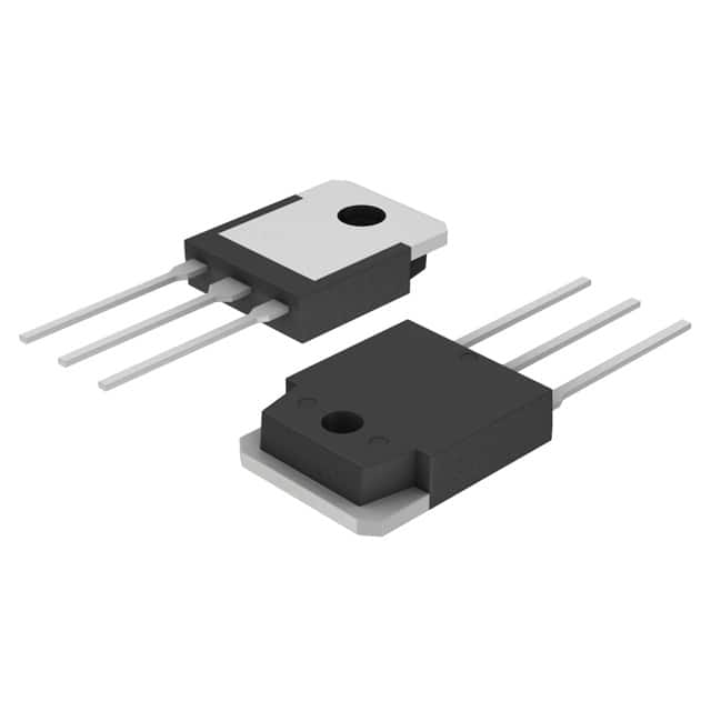
- Package: TO-3P
- Essence: The essence of the FQA140N10 lies in its ability to efficiently control high currents with minimal power loss.
- Packaging/Quantity: Typically packaged in reels or tubes containing varying quantities based on manufacturer specifications.
Specifications
- Voltage Rating: 100V
- Current Rating: 140A
- On-State Resistance (RDS(on)): 0.01Ω
- Gate Threshold Voltage: 2-4V
- Operating Temperature Range: -55°C to 175°C
- Mounting Type: Through Hole
Detailed Pin Configuration
The FQA140N10 typically features a standard pin configuration with the following pins: 1. Gate (G) 2. Drain (D) 3. Source (S)
Functional Features
- High current-carrying capability
- Low on-state resistance for efficient power management
- Fast switching speed for improved performance
- Robust construction for reliable operation in demanding environments
Advantages and Disadvantages
Advantages
- Efficient power handling
- Fast switching characteristics
- Suitable for high-power applications
Disadvantages
- Higher cost compared to lower-rated MOSFETs
- Larger physical footprint due to high current capabilities
Working Principles
The FQA140N10 operates based on the principle of field-effect transistors, where the gate voltage controls the flow of current between the drain and source terminals. When a sufficient gate voltage is applied, the MOSFET allows a high current to pass through with minimal resistance, enabling effective power control.
Detailed Application Field Plans
The FQA140N10 finds extensive use in the following applications: - Switched-mode power supplies - Motor control systems - Inverters and converters for renewable energy systems - High-current amplifiers
Detailed and Complete Alternative Models
Some alternative models to the FQA140N10 include: - IRFP4668: Similar voltage and current ratings - STP140NF75: Comparable specifications and package type - IXFN140N10: Alternative option with similar characteristics
In conclusion, the FQA140N10 power MOSFET offers high current-handling capabilities, low on-state resistance, and fast switching speed, making it suitable for various high-power applications such as power supplies and motor control systems.
[Word Count: 411]
Liệt kê 10 câu hỏi và câu trả lời thường gặp liên quan đến ứng dụng FQA140N10 trong giải pháp kỹ thuật
What is the maximum drain-source voltage of FQA140N10?
- The maximum drain-source voltage of FQA140N10 is 100V.
What is the continuous drain current rating of FQA140N10?
- The continuous drain current rating of FQA140N10 is 140A.
What is the on-resistance of FQA140N10?
- The on-resistance of FQA140N10 is typically 4.5mΩ at Vgs = 10V.
Can FQA140N10 be used in automotive applications?
- Yes, FQA140N10 is suitable for automotive applications.
What is the operating temperature range of FQA140N10?
- The operating temperature range of FQA140N10 is -55°C to 175°C.
Is FQA140N10 RoHS compliant?
- Yes, FQA140N10 is RoHS compliant.
What type of package does FQA140N10 come in?
- FQA140N10 comes in a TO-3P package.
Does FQA140N10 have built-in protection features?
- FQA140N10 does not have built-in protection features and may require external circuitry for protection.
What are the typical applications of FQA140N10?
- Typical applications of FQA140N10 include motor control, power supplies, and inverters.
What is the gate threshold voltage of FQA140N10?
- The gate threshold voltage of FQA140N10 is typically 2.0V.