

Xem thông số kỹ thuật để biết chi tiết sản phẩm.
Encyclopedia Entry: 74ACT32PC
Product Overview
Category
The 74ACT32PC belongs to the category of integrated circuits (ICs) and specifically falls under the family of logic gates.
Use
This product is commonly used in digital electronics for logical operations. It serves as a quad 2-input OR gate, allowing multiple inputs to be combined using the OR function.
Characteristics
- Quad 2-input OR gate
- High-speed operation
- Compatible with TTL input levels
- Low power consumption
- Wide operating voltage range
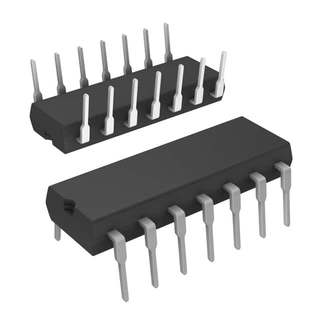
Package
The 74ACT32PC is available in a 14-pin plastic dual in-line package (DIP). This package provides protection and easy handling of the integrated circuit.
Essence
The essence of the 74ACT32PC lies in its ability to perform logical OR operations on multiple inputs, making it an essential component in various digital electronic systems.
Packaging/Quantity
The 74ACT32PC is typically sold in reels or tubes containing multiple units. The exact quantity may vary depending on the supplier.
Specifications
- Supply Voltage Range: 4.5V to 5.5V
- Input Voltage Range: 0V to VCC
- Operating Temperature Range: -40°C to +85°C
- Propagation Delay Time: 6 ns (max)
- Output Current: ±24 mA
Detailed Pin Configuration
The 74ACT32PC has a total of 14 pins, each serving a specific purpose. The pin configuration is as follows:
- Input A1
- Input B1
- Output Y1
- Ground (GND)
- Input A2
- Input B2
- Output Y2
- VCC (+5V)
- Input A3
- Input B3
- Output Y3
- Input A4
- Input B4
- Output Y4
Functional Features
- High-speed operation allows for efficient processing of logical operations.
- Compatibility with TTL input levels ensures seamless integration with existing digital systems.
- Low power consumption makes it suitable for battery-powered devices.
- Wide operating voltage range provides flexibility in various applications.
Advantages and Disadvantages
Advantages
- Fast propagation delay time enables quick response in digital circuits.
- Compatibility with TTL input levels allows for easy integration into existing systems.
- Low power consumption helps conserve energy in battery-operated devices.
Disadvantages
- Limited number of inputs (quad 2-input) may restrict the complexity of logical operations.
- Not suitable for high-voltage applications due to its operating voltage range limitations.
Working Principles
The 74ACT32PC operates based on the principles of Boolean logic, specifically the OR function. It takes two inputs and produces an output that is the logical OR of the inputs. The internal circuitry of the IC utilizes transistors and resistors to achieve this functionality.
Detailed Application Field Plans
The 74ACT32PC finds application in various fields where logical OR operations are required. Some specific areas of application include: - Digital signal processing - Computer architecture - Communication systems - Industrial automation - Robotics
Detailed and Complete Alternative Models
There are several alternative models available that offer similar functionality to the 74ACT32PC. Some notable alternatives include: - 74LS32: A low-power Schottky version of the quad 2-input OR gate. - 74HC32: A high-speed CMOS version of the quad 2-input OR gate. - CD4071: A CMOS quad 2-input OR gate with a wider supply voltage range.
These alternative models provide options for different performance requirements and compatibility with specific systems.
In conclusion, the 74ACT32PC is a quad 2-input OR gate integrated circuit that offers high-speed operation, compatibility with TTL input levels, and low power consumption. It finds application in various fields such as digital signal processing, computer architecture, and communication systems. While it has advantages in terms of speed and power consumption, its limited number of inputs and voltage range restrictions should be considered. Alternative models like the 74LS32, 74HC32, and CD4071 offer similar functionality with varying specifications to suit different needs.
Liệt kê 10 câu hỏi và câu trả lời thường gặp liên quan đến ứng dụng 74ACT32PC trong giải pháp kỹ thuật
Sure! Here are 10 common questions and answers related to the application of 74ACT32PC in technical solutions:
Q: What is the 74ACT32PC? A: The 74ACT32PC is a quad 2-input OR gate integrated circuit (IC) that is commonly used in digital logic circuits.
Q: What is the purpose of the 74ACT32PC? A: The 74ACT32PC is used to perform logical OR operations on two input signals, producing an output signal based on their logical combination.
Q: What voltage levels does the 74ACT32PC support? A: The 74ACT32PC supports a wide range of voltage levels, typically from 2V to 6V.
Q: How many OR gates are there in the 74ACT32PC? A: The 74ACT32PC contains four independent OR gates, each with two inputs and one output.
Q: Can the 74ACT32PC be used for both TTL and CMOS applications? A: Yes, the 74ACT32PC is compatible with both TTL (Transistor-Transistor Logic) and CMOS (Complementary Metal-Oxide-Semiconductor) logic families.
Q: What is the maximum operating frequency of the 74ACT32PC? A: The maximum operating frequency of the 74ACT32PC is typically around 200 MHz.
Q: Can the 74ACT32PC be used as a buffer or amplifier? A: No, the 74ACT32PC is specifically designed for performing logical OR operations and is not suitable for use as a buffer or amplifier.
Q: What is the power supply voltage range for the 74ACT32PC? A: The power supply voltage range for the 74ACT32PC is typically between 4.5V and 5.5V.
Q: Can the 74ACT32PC be used in high-speed applications? A: Yes, the 74ACT32PC is known for its fast switching speed and can be used in high-speed digital circuits.
Q: Are there any specific precautions to consider when using the 74ACT32PC? A: It is important to ensure that the input voltages do not exceed the power supply voltage range specified for the IC to prevent damage. Additionally, proper decoupling capacitors should be used to minimize noise and stabilize the power supply.