

Xem thông số kỹ thuật để biết chi tiết sản phẩm.
HEF4069UBP,652
Basic Information Overview
- Category: Integrated Circuit (IC)
- Use: Logic Gate
- Characteristics: Hex Inverter
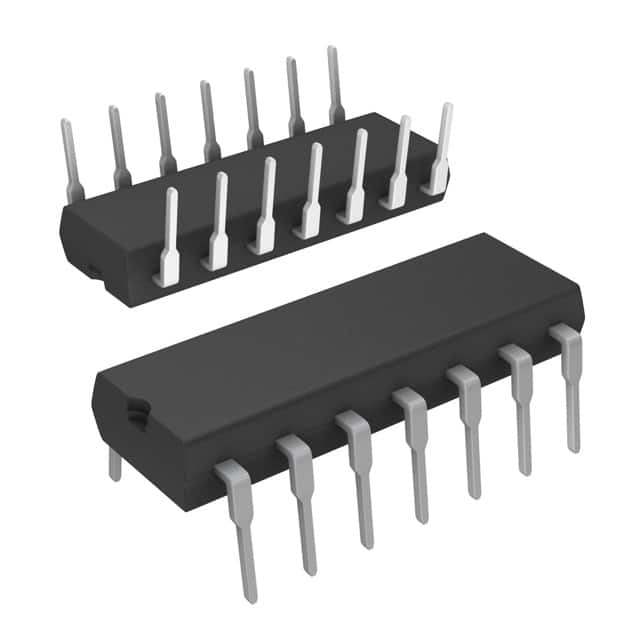
- Package: Plastic Dual In-Line Package (PDIP)
- Essence: High-speed CMOS technology
- Packaging/Quantity: Tube/50 pieces per tube
Specifications
- Supply Voltage Range: 3V to 15V
- Input Voltage Range: 0V to VDD
- Output Voltage Range: 0V to VDD
- Maximum Operating Frequency: 14 MHz
- Propagation Delay Time: 60 ns (typical)
Detailed Pin Configuration
The HEF4069UBP,652 has a total of 14 pins. The pin configuration is as follows:
Pin 1: Input A (Inverter 1)
Pin 2: Output Y (Inverter 1)
Pin 3: Input B (Inverter 2)
Pin 4: Output Y (Inverter 2)
Pin 5: Input C (Inverter 3)
Pin 6: Output Y (Inverter 3)
Pin 7: Ground (GND)
Pin 8: Power Supply (VDD)
Pin 9: Output Y (Inverter 4)
Pin 10: Input D (Inverter 4)
Pin 11: Output Y (Inverter 5)
Pin 12: Input E (Inverter 5)
Pin 13: Output Y (Inverter 6)
Pin 14: Input F (Inverter 6)
Functional Features
- Hex inverter with high noise immunity
- Wide supply voltage range allows compatibility with various systems
- Fast switching speed for efficient operation
- Low power consumption
- High output current capability
Advantages and Disadvantages
Advantages: - High-speed CMOS technology ensures reliable performance - Wide supply voltage range allows flexibility in different applications - Low power consumption makes it suitable for battery-powered devices
Disadvantages: - Limited maximum operating frequency compared to some other logic gates - Propagation delay time may affect timing-sensitive applications
Working Principles
The HEF4069UBP,652 is a hex inverter IC that utilizes high-speed CMOS technology. It consists of six independent inverters, each with one input and one output. The input signal is inverted at the output, i.e., a logical high input results in a logical low output, and vice versa. The IC operates within a wide supply voltage range and provides fast switching speed while consuming low power.
Detailed Application Field Plans
The HEF4069UBP,652 can be used in various digital logic applications, including but not limited to: - Signal inversion - Oscillators - Clock generation - Logic level shifting - Buffering
Detailed and Complete Alternative Models
Some alternative models that can be considered as replacements for the HEF4069UBP,652 are: - CD4069UB: Similar hex inverter IC from Texas Instruments - MC14069UB: Hex inverter IC from ON Semiconductor - 74HC04: Hex inverter IC from NXP Semiconductors
These alternative models offer similar functionality and can be used interchangeably depending on availability and specific requirements.
Word count: 309 words
Liệt kê 10 câu hỏi và câu trả lời thường gặp liên quan đến ứng dụng HEF4069UBP,652 trong giải pháp kỹ thuật
Sure! Here are 10 common questions and answers related to the application of HEF4069UBP,652 in technical solutions:
Q: What is the HEF4069UBP,652? A: The HEF4069UBP,652 is a hex inverter integrated circuit (IC) that consists of six independent inverters.
Q: What is the purpose of an inverter IC like HEF4069UBP,652? A: An inverter IC is used to convert logic levels, typically from high to low or vice versa.
Q: What voltage levels does the HEF4069UBP,652 support? A: The HEF4069UBP,652 supports a wide range of supply voltages, typically from 3V to 15V.
Q: Can I use the HEF4069UBP,652 with both digital and analog signals? A: No, the HEF4069UBP,652 is designed for digital signals only and may not be suitable for analog applications.
Q: How much current can each inverter of the HEF4069UBP,652 source or sink? A: Each inverter of the HEF4069UBP,652 can typically source or sink up to 6 mA of current.
Q: Can I connect the outputs of the HEF4069UBP,652 directly to other ICs or devices? A: Yes, the outputs of the HEF4069UBP,652 can be connected directly to other ICs or devices, provided they operate within the same voltage range.
Q: Is the HEF4069UBP,652 tolerant to electrostatic discharge (ESD)? A: Yes, the HEF4069UBP,652 is designed to be ESD tolerant, but proper ESD precautions should still be taken during handling and assembly.
Q: Can I use the HEF4069UBP,652 in high-speed applications? A: Yes, the HEF4069UBP,652 can be used in moderate-speed digital applications, but it may not be suitable for very high-frequency applications.
Q: Are there any specific layout considerations when using the HEF4069UBP,652? A: It is recommended to follow the manufacturer's guidelines for PCB layout, including proper decoupling capacitors and minimizing trace lengths.
Q: Where can I find more information about the HEF4069UBP,652? A: You can refer to the datasheet provided by the manufacturer or visit their website for detailed information on the HEF4069UBP,652's specifications and application notes.
Please note that these answers are general and may vary depending on the specific requirements and use cases.