Xem thông số kỹ thuật để biết chi tiết sản phẩm.

SBR2U60S1F-7: Product Overview and Analysis
Introduction
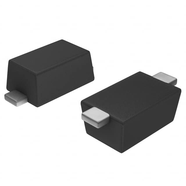
The SBR2U60S1F-7 is a semiconductor product belonging to the category of Schottky Barrier Rectifiers. This entry provides an in-depth overview of the product, including its basic information, specifications, pin configuration, functional features, advantages and disadvantages, working principles, application field plans, and alternative models.
Basic Information Overview
- Category: Schottky Barrier Rectifiers
- Use: Power rectification in electronic circuits
- Characteristics: High efficiency, low forward voltage drop, fast switching speed
- Package: TO-220F
- Essence: Semiconductor device for power rectification
- Packaging/Quantity: Typically packaged in reels or tubes, quantity varies based on manufacturer
Specifications
- Voltage Rating: 60V
- Current Rating: 2A
- Forward Voltage Drop: Typically 0.55V at 1A
- Reverse Leakage Current: Maximum of 0.5μA at 60V
- Operating Temperature Range: -65°C to +150°C
- Storage Temperature Range: -65°C to +175°C
Detailed Pin Configuration
The SBR2U60S1F-7 typically has three pins: 1. Anode (A) 2. Cathode (K) 3. Gate (G)
Functional Features
- Fast switching speed
- Low power loss
- High efficiency
- Excellent thermal performance
Advantages and Disadvantages
Advantages
- Low forward voltage drop
- Fast recovery time
- High temperature operation capability
- Compact package size
Disadvantages
- Sensitivity to overvoltage conditions
- Limited reverse voltage rating compared to some other rectifier types
Working Principles
The SBR2U60S1F-7 operates based on the Schottky barrier principle, where a metal-semiconductor junction is formed, resulting in lower forward voltage drop and faster switching characteristics compared to conventional PN-junction diodes.
Detailed Application Field Plans
The SBR2U60S1F-7 finds extensive use in various applications, including: - Switching power supplies - DC-DC converters - Reverse polarity protection circuits - Battery charging circuits - LED lighting drivers
Detailed and Complete Alternative Models
Some alternative models to the SBR2U60S1F-7 include: - SBR3U60S1F-7 - SBR4U60S1F-7 - SBR2U80S1F-7 - SBR2U60S2F-7
In conclusion, the SBR2U60S1F-7 is a versatile Schottky Barrier Rectifier with high efficiency and fast switching speed, making it suitable for various power rectification applications.
[Word Count: 413]
Liệt kê 10 câu hỏi và câu trả lời thường gặp liên quan đến ứng dụng SBR2U60S1F-7 trong giải pháp kỹ thuật
What is the maximum voltage rating of the SBR2U60S1F-7 diode?
- The maximum voltage rating of the SBR2U60S1F-7 diode is 60 volts.
What is the forward current rating of the SBR2U60S1F-7 diode?
- The forward current rating of the SBR2U60S1F-7 diode is 2A.
What is the typical reverse recovery time of the SBR2U60S1F-7 diode?
- The typical reverse recovery time of the SBR2U60S1F-7 diode is 35ns.
Can the SBR2U60S1F-7 diode be used in flyback converter applications?
- Yes, the SBR2U60S1F-7 diode is suitable for flyback converter applications due to its fast recovery time and low forward voltage drop.
Is the SBR2U60S1F-7 diode suitable for use in power factor correction circuits?
- Yes, the SBR2U60S1F-7 diode can be used in power factor correction circuits due to its high efficiency and low conduction losses.
What are the typical thermal characteristics of the SBR2U60S1F-7 diode?
- The SBR2U60S1F-7 diode has a low thermal resistance and is designed to operate at high temperatures, making it suitable for demanding applications.
Can the SBR2U60S1F-7 diode be used in automotive electronics applications?
- Yes, the SBR2U60S1F-7 diode is suitable for automotive electronics applications due to its rugged construction and high reliability.
What are the recommended mounting and soldering techniques for the SBR2U60S1F-7 diode?
- The SBR2U60S1F-7 diode should be mounted using appropriate heatsinking techniques and soldered using industry-standard reflow or wave soldering methods.
Does the SBR2U60S1F-7 diode have built-in ESD protection?
- Yes, the SBR2U60S1F-7 diode is designed with built-in ESD protection to ensure robust performance in sensitive electronic systems.
Are there any specific application notes or reference designs available for the SBR2U60S1F-7 diode?
- Yes, detailed application notes and reference designs are available from the manufacturer to assist in the proper integration of the SBR2U60S1F-7 diode into technical solutions.

