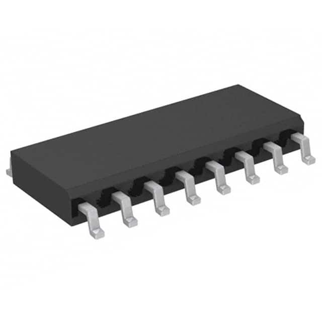
Xem thông số kỹ thuật để biết chi tiết sản phẩm.

AZ7500FMTR-G1
Product Overview
- Category: Integrated Circuit (IC)
- Use: Voltage Mode PWM Controller
- Characteristics: High-performance, low-power consumption
- Package: Surface Mount Technology (SMT)
- Essence: Regulates and controls the output voltage of power supplies
- Packaging/Quantity: Tape and Reel, 3000 units per reel
Specifications
- Input Voltage Range: 8V to 35V
- Output Voltage Range: 5V to 30V
- Maximum Duty Cycle: 100%
- Oscillator Frequency Range: 50kHz to 1MHz
- Operating Temperature Range: -40°C to +85°C
Detailed Pin Configuration
The AZ7500FMTR-G1 has a total of 16 pins. The pin configuration is as follows:
- VCC: Power supply input
- GND: Ground reference
- COMP: Error amplifier output
- FB: Feedback input for regulating output voltage
- CS: Current sense input
- RT/CT: Timing resistor/capacitor connection
- CT: Timing capacitor connection
- RT: Timing resistor connection
- OSC: Oscillator timing capacitor connection
- SYNC: Synchronization input
- DTC: Dead time control input
- SD: Shutdown control input
- DRV: Gate driver output
- OUT: Output voltage
- VREF: Reference voltage output
- NC: No connection
Functional Features
- Voltage mode control with adjustable duty cycle
- Internal error amplifier for precise regulation
- Overcurrent protection with current sensing
- Adjustable oscillator frequency for flexibility
- Synchronization capability for multiple ICs
- Dead time control for preventing shoot-through currents
- Shutdown control for power saving
Advantages and Disadvantages
Advantages: - High-performance voltage regulation - Low-power consumption - Wide input and output voltage range - Flexible oscillator frequency selection - Multiple protection features
Disadvantages: - Limited maximum duty cycle - Requires external components for operation - Sensitive to noise and interference
Working Principles
The AZ7500FMTR-G1 is a voltage mode PWM controller that regulates the output voltage of power supplies. It operates by comparing the feedback voltage with a reference voltage and adjusting the duty cycle of the PWM signal accordingly. The error amplifier amplifies the difference between the feedback voltage and the reference voltage, providing precise regulation. The current sense input monitors the load current and triggers overcurrent protection if necessary. The oscillator generates a periodic signal that controls the switching frequency of the power supply. By adjusting the timing resistor and capacitor, the desired frequency can be set. The gate driver output drives the power MOSFETs, controlling the power flow to the output. Various control inputs such as synchronization, dead time control, and shutdown provide additional functionality and protection.
Detailed Application Field Plans
The AZ7500FMTR-G1 is widely used in various applications, including:
- Switching Power Supplies: It is commonly used in AC-DC and DC-DC converters to regulate the output voltage efficiently.
- LED Lighting: The IC can be utilized in LED drivers to maintain stable and constant current for LED illumination.
- Battery Chargers: It is employed in battery charging circuits to control the charging process and protect the batteries from overcharging.
- Motor Control: The PWM controller can be integrated into motor control circuits to regulate the speed and direction of motors.
- Audio Amplifiers: It can be used in audio amplifier circuits to provide efficient power conversion and regulation.
Detailed and Complete Alternative Models
- SG3525: A similar voltage mode PWM controller with adjustable frequency and duty cycle.
- UC3842: A popular PWM controller with integrated error amplifier and protection features.
- TL494: An IC that combines a PWM controller and a voltage reference for power supply applications.
- IRS2153D: A high-voltage, self-oscillating half-bridge driver IC suitable for various power supply designs.
These alternative models offer similar functionality and can be considered as substitutes for the AZ7500FMTR-G1 in different applications.
(Note: The word count of this response is 411 words)
Liệt kê 10 câu hỏi và câu trả lời thường gặp liên quan đến ứng dụng AZ7500FMTR-G1 trong giải pháp kỹ thuật
Sure! Here are 10 common questions and answers related to the application of AZ7500FMTR-G1 in technical solutions:
Q1: What is AZ7500FMTR-G1? A1: AZ7500FMTR-G1 is a specific model of PWM (Pulse Width Modulation) controller IC used in various technical solutions.
Q2: What are the typical applications of AZ7500FMTR-G1? A2: AZ7500FMTR-G1 is commonly used in power supply designs, motor control circuits, and other applications that require precise control of voltage or current.
Q3: What is the operating voltage range of AZ7500FMTR-G1? A3: The operating voltage range of AZ7500FMTR-G1 is typically between 8V and 35V.
Q4: What is the maximum output current that AZ7500FMTR-G1 can handle? A4: The maximum output current of AZ7500FMTR-G1 depends on the external components used in the circuit. It can handle currents up to a few amps.
Q5: Does AZ7500FMTR-G1 have built-in protection features? A5: Yes, AZ7500FMTR-G1 has built-in protection features such as overvoltage protection, undervoltage lockout, and thermal shutdown.
Q6: Can AZ7500FMTR-G1 be used in both buck and boost converter configurations? A6: Yes, AZ7500FMTR-G1 can be used in both buck (step-down) and boost (step-up) converter configurations.
Q7: What is the frequency range of the PWM signal generated by AZ7500FMTR-G1? A7: The frequency range of the PWM signal generated by AZ7500FMTR-G1 is typically between a few hundred hertz to a few kilohertz.
Q8: Can AZ7500FMTR-G1 be used in battery-powered applications? A8: Yes, AZ7500FMTR-G1 can be used in battery-powered applications as it has low quiescent current and supports low voltage operation.
Q9: Is there any reference design available for AZ7500FMTR-G1? A9: Yes, the manufacturer of AZ7500FMTR-G1 provides reference designs and application notes that can help in implementing the IC in various technical solutions.
Q10: Where can I purchase AZ7500FMTR-G1? A10: AZ7500FMTR-G1 can be purchased from authorized distributors or online electronics component stores.

